Dewei Chuang OXYGEN software synchronization settings

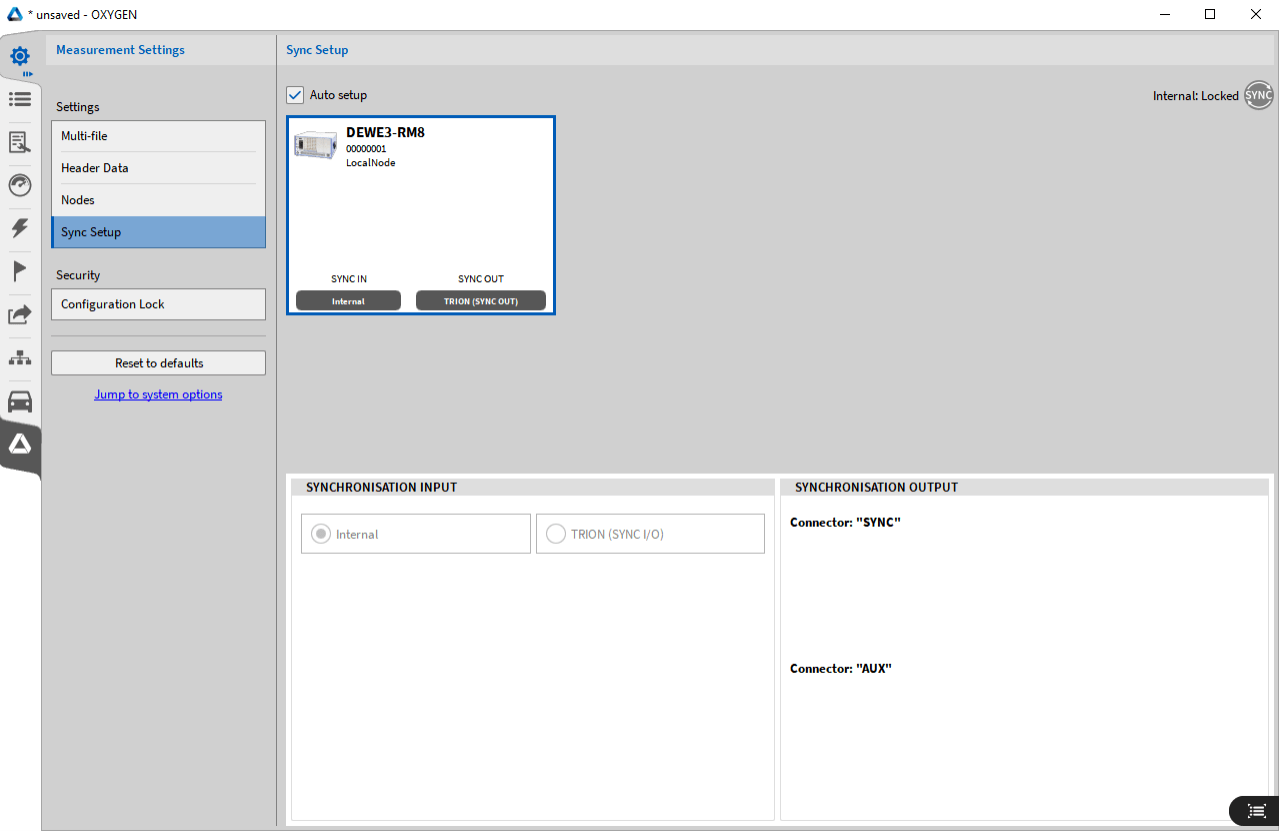
Fig. 5.27: Synchronization Setting Interface
The following section provides information on various synchronization options using OXYGEN and TRION hardware. With DEWE2/3 instruments, there is almost no limit when the systems are synchronized with each other. The synchronization of equipment can be completed either through an internal 10mhz clock, or through TRION-SYNC-BUS (synchronous I/O, synchronous out), IRIG, PPS, PTP/IEE1588 or GPS. The synchronization options depend on the model and configuration of the DEWE2/3 instrument.
• Synchronous input indicates how a device's input configuration to the instrument "acquires" or "generates" an input signal from any source
• Synchronous output represents the output configuration of the device, which defines what kind of signal the instrument will correspond to the corresponding output to synchronize with the next connected device.
Internal clock source
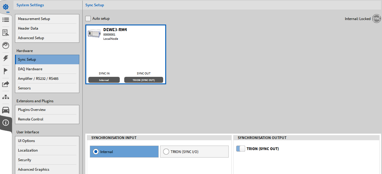
Each DEWE2/3 chassis has an internal 10MHz clock, which is used as the clock source of the DEWE2/3 system. By default, this internal clock is used for synchronization. Therefore, the automatic setting box is selected by default, and the internal clock is selected as the synchronization input source (refer to Figure 5.28)

Fig. 5.28: Selection of internal clock for synchronous setting
If the "internal clock" is used for synchronization, the "synchronization" indicator in the upper right corner of the menu will turn gray.
TRION-SYNC-BUS
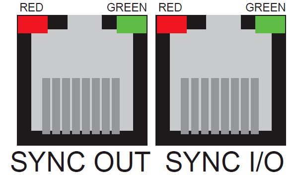
In addition, each DEWE2/3 system can output the synchronization signal of 10MHz clock and send it to another DEWE2/3 system. This is the function of the SYNC I/O connector on the system (refer to Figure 5.29)

Fig. 5.29: Synchronization Interface of DEWE2/3 System
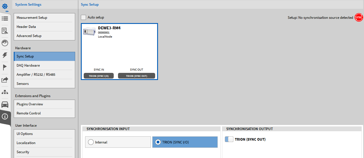
Synchronization signal forwarding can only be used with OXYGEN-NET option. One interface is output as synchronous signal, and the other interface can be used as input or output interface T synchronous signal is sent automatically; Refer to (Figure 5.28) and cannot be closed. In order to synchronize with other DEWE2/3 systems, the DEWE2/3 system needs to be configured as follows: uncheck the automatic setting box, and set the synchronization input source to TRION (refer to Figure 5.30)

Fig. 5.30: Selection of Synchronization Settings TRION-SYNC-BUS
Color of synchronization indicator in the upper right corner of the menu:
• Red, no valid synchronization signal is connected to SYNC I/O interface
• Orange, effective synchronization signal is connected to SYNC I/O interface, but the system is not locked (it will be locked automatically in a few seconds)
• Green, effective synchronization signal is involved in SYNC I/O interface and the system is locked.
If the synchronization setting is turned off, the synchronization indicator can also be used in the operation bar (refer to ② Figure 3.1) The indicators of SYNC OUT and SYNC I/O interfaces are defined as follows:

Table 5.1: Synchronization interface indicator
Depending on the use of SYNCI/O (input or output), the indicator indicates whether the system clock is available or whether the clock signal received from another system is correct. The green LED indicates that data acquisition is running. If recording stops, the LED will be off. Depending on the board in the first slot of the system, different synchronization signals are applied to the system
The application of the external clock of the DEWE2/3 system depends on the board installed in the first slot of the system. Different external clock signals can be applied in the system. Table 5.2 below provides a preview of different synchronization signals for different boards:
Table 5.2: TRION board and synchronization signal

TRION-BASE synchronization
The first slot of the system is installed with a TRION-BASE board card. The system synchronization can be achieved through the external IRIG-B-DC or PPS signal (rising edge synchronization) IRIG-B-DC or PPS as synchronization signal. Insert the signal into the IRIGin channel of the board (the PPS signal must be input through the IRIG connector) Cancel the "Automatic setting" box in "Synchronization setting", and select "IRIG" or "PPS" in the "Synchronization input" menu (refer to Figure 5.31)
Fig. 5.31: Selecting External Synchronization Clock Signal when Synchronizing with TRION-BASE
Synchronization indicator in the menu:
• Red, no synchronous signal is connected to SYNC I/O interface
• Orange, synchronization signal is connected but the system is not locked (the system will lock automatically after a few seconds)
• Green, effective synchronization signal is connected and the system is locked
If the synchronization setting is turned off, the synchronization indicator can also be used in the operation bar (refer to ② Figure 3.1) Note: When an external clock signal enters the system, the t signal can be forwarded through the TRION-SYNC-BUS bus (refer to TRION-SYNC-BUS) to synchronize other DEWE2/3 systems. In addition, the TRION base board has an AUX connector that can output a rectangular (LVTTL) signal to synchronize other devices, such as GigE cameras, to the TRION hardware clock. To do this, enable the frequency (AUX) switch in the synchronous output setting (refer to Figure 5.32) "Frequency" can be set as 10hz~10mhz, and "Start edge" can be set as "rising" or "falling" signal. Fig. 5.32: LVTTL signal TRION-TIMING/VGPS synchronization is provided through the AUX connector of the TRION-BASE board. If the TRION-TIMING or TRION-VGPS board is installed in the first slot of the system, the system can be synchronized with external IRIG (a - dc, a - ac, B-DC, B-AC) or PPS signals (synchronized to the rising edge signal; only the TRION-TIMING/VGPS-V3 board can be synchronized to the falling signal edge).
IRIG uses IRIG signal as synchronization signal, and connects this signal to IRIG input terminal of TRION board. Cancel the automatic setting box in the synchronization setting, and select IRIG in the synchronization input menu (refer to Figure 5.35) Go to the IrigCode drop-down menu and select the correct Irig code (refer to Figure 5.33). The TRION-TIMING/VGPS-V3 board also supports IRIG B-DC signal output. This can be found under Sync Output Settings>Connector: AUX>IRIG.
PPS uses PPS signal as synchronization signal, and connects the signal to IRIG input terminal of TRION board (PPS signal must be input through IRIG connector). Cancel the "Automatic setting" box in "Synchronization setting", and select "PPS" in the "Synchronization input" menu (refer to Figure 5.35) The system selects the rising edge signal synchronization, and the reverse output option selects Cancel. If the system selects the falling edge signal synchronization, the reverse output option selects Confirm Note: Only the TRION-TIMING/VGPS-V3 board supports PPS falling edge synchronization
GPS synchronization If you want to synchronize through GPS, connect the synchronization line to the GPS board card Uncheck the Auto button and select the GPS synchronization option
PTP/IEEE 1588 Note: Only the TRION-TIMING/VGPS-V3 board supports PTP synchronization. If PTP is used for synchronization, connect the synchronization line to the PTP i input port. Cancel the automatic option and select the PTP synchronization button
Color identification of synchronization indicator in the upper right corner:
• Red, no correct synchronization signal is connected to SYNC I/O interface
• Orange, the correct synchronization signal is connected to the SYNC I/O interface, but the system is not locked (automatically locked in a few seconds)
• Green, the correct synchronization signal is connected to the SYNC I/O interface and the system is locked
The synchronization indicator will also be displayed in the toolbar below the acquisition interface (see ② Figure 3.1) Note: If an external synchronization signal is connected to the system, the signal can be transmitted through TRION-SYNC-BUS (see TRION-SYNC-BUS) a to synchronize the DEWE2/3 chassis system In addition, the AUX interface on the TRION-TIMING/VGPS board can output external (LVTTL) signals to synchronize external devices, such as the GigE camera, to the TRION hardware clock. To achieve this function, turn on the AUX synchronization switch in the synchronous output function (see Figure 5.32) The frequency setting from 10 Hz to 10 MHz can start with rising or falling signals
General description of PPS and IRIG synchronization:
• PPS PPS is an abbreviation for pulse per second. PPS signal provides one pulse per second for data synchronization using rising edge or falling edge.
• The PPS signal is generally provided by the GPS receiver or inertial navigation system with GeneSys ADMA's or OxTS RT's
• IRIG time code is used to control the phase-locked loop, and then the phase-locked loop is used as the time base of the system
• The IRIG connector also has an indicator LED that flashes green or red


