Modal test is used to determine the natural frequency, mode shape or damping ratio of a structure or object. Modal test is a crucial process, especially in the field of construction technology and mechanical engineering. From the automotive industry to aerospace, modal testing plays an important role in ensuring the integrity, safety and performance of individual components and the entire structure.

What is modal test?
Modal test is a form of vibration test, which can determine the modal parameters of the structure through experiments. For example, modal tests are used to analyze aircraft components, chassis, engines, wind turbines, or to verify any other structural components. Particularly important modal parameters are:
Natural (or modal) frequency
They represent the frequency at which the structure oscillates under dynamic loads without any external force. These frequencies are inherent to the system and depend on the mass, stiffness and damping characteristics of the system.
Damping ratio
They quantified the rate at which structural vibration decayed over time. Damping is essential to understand the energy dissipation and stability of the system under dynamic load conditions.
Modal shape
They represent the spatial distribution of displacement or deformation within the structure under a certain natural frequency. They provide information about the vibration modes and dynamic behavior of the system.
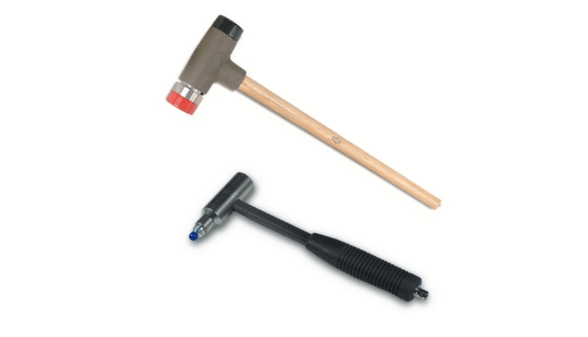
Modal analysis focuses on parameter analysis, and modal test focuses on data acquisition. Modal testing includes many methods, and impact testing is one of the commonly used techniques. This includes applying a controlled mechanical force to the DUT through an exciter and measuring the resulting response. Typically, a modal hammer is used to apply this controlled force. These hammers integrate IEPE sensors on their striking surfaces to accurately measure force. At the same time, the DUT response is captured using an accelerometer or other vibration sensor.

Depending on the device under test (DUT), test setup, and test environment, the method includes the use of single or multiple exciters and single or multiple response sensors. This provides three different and useful test configurations:
1. Single Input Single Output:
In SISO testing, a single actuator (e.g. hammer) and a single sensor are used. The operator can choose to move the exciter while keeping the response sensor fixed and vice versa. Depending on the application, this setting is called a moving hammer or a moving sensor test.
2. Single Input Multiple Output:
SIMO settings include a single (mobile) actuator and multiple sensors that capture responses. This configuration allows simultaneous measurement of a single excitation at different sensor locations, providing comprehensive data on the behavior of the device under test.
3. Multiple input multiple output (MIMO):
In MIMO configuration, multiple actuators and multiple response sensors are used. Typically, the exciter acts as an exciter in MIMO testing, providing versatility and being able to evaluate complex interactions across different excitation points and response locations within the DUT.
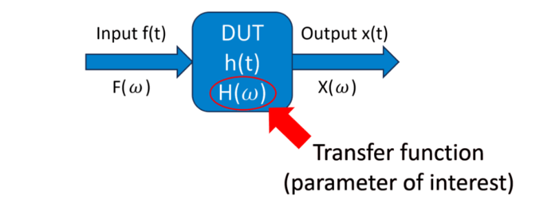
In the case of resonance, the amplification of the response can be seen in the response spectrum. On the basis of this response spectrum, combined with the force spectrum, we can get the transfer function, especially the frequency response function (FRF), which is the parameter we are interested in. The frequency response then allows quantifying the relationship between the input and output signals at each frequency. There are various algorithms for calculating the frequency response, all of which are usually executed in the frequency space, because this greatly simplifies the entire calculation. For more information about different calculation algorithms, please see our modal test manual.

Advanced analysis techniques such as modal indicator function (MIF) or curve fitting can enhance the understanding of frequency response function (frf) by promoting the estimation of modal parameters. When MIF evaluates the frequency response on all excitation paths to identify modes, curve fitting estimates modal parameters, such as natural frequency or damping coefficient. However, since MIF and curve fitting are inherent parts of modal analysis rather than modal testing, this blog post will not delve into these analysis techniques.
What are the applications of modal testing?
Modal testing and further modal analysis are common tools implemented in various engineering disciplines and industries. Here are some notable examples:
automobile
In the automotive field, modal testing evaluates the vibration characteristics of vehicle components and chassis systems, which is crucial to the analysis of ride comfort and durability.
civil engineering
Modal tests allow the evaluation of the dynamic behavior of large structures, such as buildings, bridges, dams, or other structures, under wind, earthquake, or operating loads.
Aerospace
Modal test plays a key role in analyzing the dynamic performance of aircraft components, such as wings, fuselage and control surfaces, and contributes to the optimization of aircraft structures.
mechanical system
Modal testing measures the vibration modes of machines and industrial systems. In the further process, this helps to prevent fatigue failure and optimize performance.
OXYGEN modal test
With the release of OXYGEN 7.0, we implemented modal testing in the intuitive measurement software OXYGEN. In this way, the moving hammer and the moving sensor can be used to conduct SISO and SIMO tests, and to calculate the complex transfer function, the coherence of multiple hits, and the mode indicator function (MIF). In addition, we also realized various interactive visualization options and the possibility of importing 3D geometric models.
In the following, we provide a step-by-step quick guide on how to use the DEWETRON measurement system for modal testing in OXYGEN. For a comprehensive explanation, refer again to the Technical Reference.
Quick Guide - Modal Testing
Modal testing and OXYGEN 7.0 are so easy, Test bench As the tested equipment. The system is excited by a modal hammer, and the response signals are measured at multiple locations by an accelerometer. The signal from the sensor is recorded by our data acquisition system NEX [DAQ].


