This paper mainly introduces how to design a multi-channel synchronous high-speed data acquisition system according to the given sensor types and the actual working conditions on site.
1、 Test system function and purpose
DVC multi-channel strain data acquisition system is mainly used to collect and record the strain, voltage, vibration and other parameters of the whole test site system. The data acquisition system is mainly composed of acquisition equipment, computer and calibration source.
2、 Main technical requirements of DVI Data Acquisition System
※ Channel number: strain 96;
※ Bus type: PXI bus
※ Parameter type: strain/voltage, IEPE, thermocouple, platinum resistance, etc;
※ Sampling rate: strain signal acquisition shall not be less than 200kS/s;
※ Signal isolation: channels are isolated from each other;
※ Input overvoltage protection, sensor open circuit detection function;
※ The pressure flow channel can measure the full bridge, half bridge, 1/4 bridge and voltage;
※ Excitation voltage: 0~13V (supply range of optional modules: 0-24V adjustable), adjustable by grades, stability better than 0.05%;
※ Thermocouple sensor: support K, J, T, E, R, S, B, N, C, U, etc,
※ RTD input: Pt100, Pt200, Pt500, Pt1000 or Pt2000 sensor,
※ Corresponding equipment driver software and interface functions shall be provided to facilitate software development. Provide test software and original data file analysis software to facilitate acceptance and commissioning; The acquisition equipment is equipped with relevant accessories, 50 meter cables and connectors.

3、 Product advantages of DEWETRON data acquisition system
In the design and implementation of this scheme, the excitation, signal adjustment, recording, analysis and processing scheme of the test sensor are designed to be universal and forward-looking, and priority is given to ensuring the core and general needs that need to be solved urgently in the actual test, that is, "solve user application problems with universal methods". For practical purposes; In order to facilitate the user's test and analysis, improve the system efficiency and shorten the test and analysis cycle; Based on solving key core needs; At the same time, the system is advanced and forward-looking.
This scheme uses the acquisition and analysis system of Dewetron (Austria) as the test platform.
Dewetron is a world-famous manufacturer of data acquisition, adjustment and analysis systems. Its multi-channel combined data acquisition and analysis systems and highly portable instruments are world-renowned. DEWETRON has always been known for its stable and reliable product quality and excellent cost performance. At present, DEWETRON has become a major manufacturer of signal adjustment and test instruments based on the open IPC platform. DEWETRON has branches in more than 30 places around the world, mainly providing various portable data acquisition systems, including test systems, data recorders, data acquisition systems, dynamic signal analyzers, transient recorders, combustion analyzers, power quality analyzers, and other supporting software for aerospace, weapons, and vehicles. In China, the acquisition system of DEWETRON is basically used by research institutes and manufacturers in aerospace, weapons and power industries. It has solved many problems for customer's scientific research and production, and has been highly praised by users. With the rapid development of data acquisition and testing systems, Devtrong provides more and more powerful and cost-effective data acquisition systems, which replace traditional testing instruments. Tens of thousands of accurate testing systems are currently serving testing units in various fields around the world, and the user list is growing rapidly With good performance price ratio and high quality and efficient after-sales service, Devtrong is providing more and more testing units with thoughtful and fast testing experience.
3.1 Strong advantages of Dewei Chuang data acquisition system
It can directly provide excitation voltage 0-24V (or current) for the sensor;
The acquisition system integrates signal adjustment, storage and analysis to ensure the stability and high accuracy of the system.
It can not only work in a large system, but also work in a distributed and independent manner for each subsystem. It can flexibly choose a variety of working modes and data storage modes according to test needs;
The new product adopts PXI bus architecture, which can complete each acquisition task more reliably and in real time.
High integration and high precision signal adjustment module (0.05% adjustment precision) ensures the high precision of the whole test chain;
With advanced filtering technology, the anti aliasing filtering effect is far greater than that of the 10 order ordinary filter;
Advanced analysis function supports real-time analysis and processing of stored data during data recording;
Reliable isolation between channels and between channels and chassis ensures high anti-interference of the system;
Powerful system acquisition and analysis software can synchronously process and replay analog signals and high-speed video signals, making the test process clear at a glance;
The virtual channel can transform and calculate various physical quantities in real time, which is very convenient for online observation of data processing results, and greatly saves data post-processing time (industry priority);
The industry is the first to realize the construction of a networked test system, which supports the function of host computer to remotely control the acquisition terminal.
Alloy metal shell, EMI (electromagnetic interference) and RFI (radio frequency interference) are difficult to pass through, thus greatly reducing the test system error;
The anti vibration and impact characteristics of the system comply with MIL-STD-810F; Anti electromagnetic interference conforms to CE standard and is suitable for engineering test requirements in complex environment;
4、 System composition and architecture
The design of the data acquisition system follows the principles of practicality, reliability and advancement. The PXI bus test technology, which is preferred at home and abroad, is adopted. In terms of the design of the software and hardware of the system, the design idea of generalization, modularization and serialization is followed to realize the high reliability and high integration of the data acquisition system in the test.

In order to make the test system compact, stable and reliable, and convenient to use at the same time, the test system adopts a step-by-step network structure in structure. The data acquisition equipment is placed on the test site, the operation control and data storage service computer and the data acquisition and data analysis computer are placed in the test room, and they are connected by network cable (recommended network cable length is within 150 meters), This greatly reduces the length of the test cable from the sensor to the test cabinet. At the same time, it can also ensure the convenient and reliable operation of the whole system.
The hardware of the test system is mainly composed of various sensors, test cables, signal adjustment devices (if necessary), and data acquisition systems.
The hardware of the data acquisition system is mainly composed of the following parts:
a) Various sensors;
b) Test cable;
c) Signal adjustment device (if necessary);
d) Data acquisition system (including computer part);
During the test, the signal adjustment device supplies power to various sensors, and transmits the output signal to the data acquisition system and the master control system. The master computer controls the start and stop of the test and data acquisition and transmission.
4.1 System principle
The compact multi-function test system hardware adopts a solid and compact design structure, with each test module as the basic hardware framework; In the design of the test system, the requirements of high reliability, ease of use, maintainability and compatibility with the existing system should be taken into account. At the same time, due to the complexity of the test site, the system is required to have the characteristics of high density, modularization and networking to improve the integration and reliability of the system.
This scheme strives to be universal and forward-looking in design, and gives priority to the core and general requirements that need to be solved urgently in the actual test, that is, "solve problems with universal methods". For practical purposes; In order to facilitate test analysis, improve system efficiency and shorten the test data analysis cycle; Based on solving key core needs; At the same time, the system is advanced and forward-looking.
The hardware design will adopt mature test technology to improve the test speed and reliability; Reduce the volume of the test system; Balance system load; Expand the application scope and flexibility of the system.
In the software design, the framework test software structure is adopted; Modular independent function packaging; The management of engineering parameters, test flow, virtual instruments and measurement result data is carried out by executing test software; Thus, the universality and maintainability of the system are greatly improved; It facilitates the processing of test result data, reduces the work intensity of testers, improves the reliability of testing, and reduces the degree of test repetition. Thus, the test cost is reduced, the development time of the test system is shortened, and the risk is reduced to a lower limit.
The compact multi-function test system consists of a computer, a data acquisition system, test cables, sensors and other parts. Test parameters include strain, temperature, etc.
In the test, the signal adjustment module supplies power to all kinds of sensors through the test cable, and transmits the output signal to the data acquisition system. The main control computer (upper computer) can control the start and stop of the test and data acquisition and transmission.
The acquisition system adopts built-in precision signal adjustment module, which can be directly connected with various sensors. Its AC isolation and symmetrical floating ground differential input mode can ensure high-precision, interference free precision measurement in various environments. The detection of all program control modules is automatically completed by the test software. The user only needs to input the sensor sensitivity and test range to test. The software adopts test software, which has a good man-machine interface and multiple trigger modes to ensure that the test results can be obtained under the set test conditions. The single module sampling rate setting function can save a lot of disk space; FFT, various mathematical operation functions can directly obtain the calculation results.
4.2 System composition
96 channel multi-function test system includes a host DEWE2-M18 test system host,
12 TRION-2402-DSTG-8 multi-function modules (signal adjustment, A/D conversion integrated module).
System 1 hardware configuration is shown in the following table:
S/N Hardware function quantity
1 DEWE2-M18 128 channel test system host, including desktop computer 1
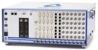
3 TRION-2402-dSTG-8-L0B multi-function adjustment module 8-channel multi-function conditioning board card, multi-function acquisition adjustment module, sampling rate 200ks/s per channel

seven OXYGEN Acquisition software 1
8 Opt net distributed networking software option 1
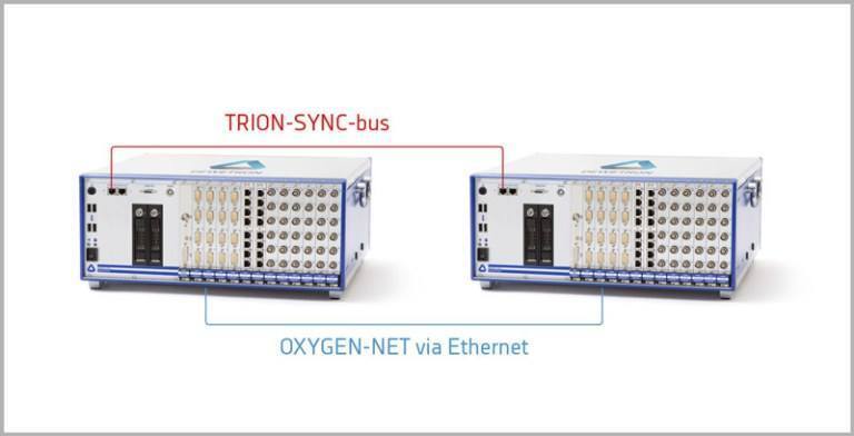
4.3 System composition structure
In order to make the test system structure lightweight, the system structure adopts the following design scheme. The principle is as follows:
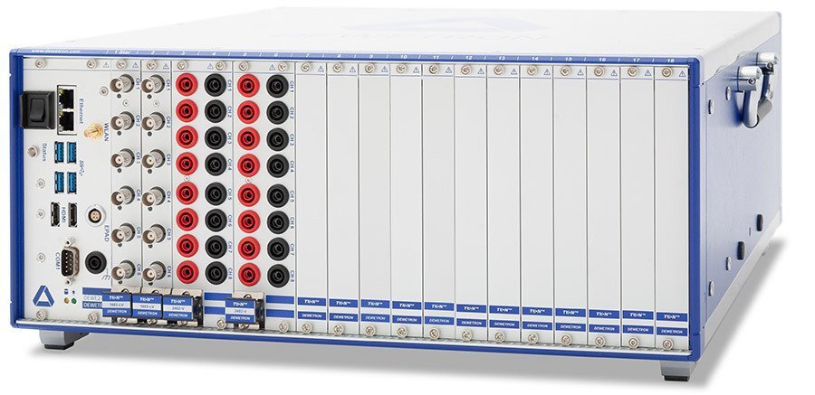
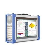
4.3.2 The product is shown in the following figure:
DEWE2-M18 host
DEWE2-A4 host
DEWE2-A7 or DEWE2-A13 host
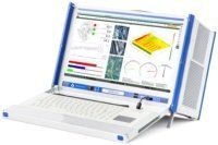
Features: light and compact, suitable for laboratory and outfield testing.
Compact PXI Bus Data Acquisition System
• Integrated design, solid PXI bus data acquisition system
• 18 TRION module slots
• One PCIe 1X interface and two TRION-SYNC-BUS interfaces.
• Configure mainstream displays
• Intel ® CoRE ™ I7 processor, 16GB memory, 256GB SSD industrial solid state disk.
• Large data storage rate is 90 MB/s, 4 USB interfaces, 2 LAN Ethernet interfaces, 1 RS-232 interface, 1 EPAD interface (Lemo EGG. 1B. 304), and 2 HDMI interfaces.
• Power supply 115/230VAC
Solid state hard disk pluggable
Can support battery power supply
4.3.3 TRION module (signal adjustment, A/D conversion integrated board)
Model: TRION-2402-dSTG-8-L0B multi-function adjustment module
8-channel isolated voltage channel, 24 bit resolution, synchronous acquisition, each channel with anti aliasing filter
204.8 kS/s per channel, bandwidth: DC to 77 kHz
Directly measure bridge circuit, ± 10 V voltage, IEPE, RTD, resistance and current signal.
Four high pass filtering options: 0.16, 0.5, 3.4 and 10 Hz
Programmable excitation voltage: 0 ~ 13 VDC (program-controlled, 16 Bit DAC) (can be defined as+5V power supply through wiring), 100mA ZUI high current and 8W ZUI high power for each module
Programmable excitation current: 200 µ A - 25 mA
Bridge input: full bridge sensor: 80 Ohm-10 kOhm (exception ≤ 5 V)
Internal bridge: half bridge sensor: 80 Ohm-10 kOhm
Internal bridge: 1/4 bridge sensor: 120 and 350 Ohm
Strain input range: ± 1 to ± 1000 mV/V (equivalent to ± 2000 to ± 2000000 microstrain) or mV/mA
IEPE input: 100mv-10v
Voltage input range: ± 10 mV to ± 10V
RTD input: Pt100, Pt200, Pt500, Pt1000 or Pt2000 sensor
Interface: 8 * Lemo
Table 1 Interface definition of resistance strain gauge
Pin TRION-2402-DSTG-8-L0B multi-function adjustment module 9-pin socket sensor output LEMO 9-pin plug corresponding sensor
1 1EXC+power supply+strain sensor or voltage signal
2 IN+empty
3 Sense signal-
4 GND empty
5 R+empty
6 Sense+signal+
7 IN Empty
8 EXC Power-
9 TEDS empty
4.4 Test software
The data acquisition system adopts OXYGEN, which supports users' self-development.
• Functions of data acquisition software
• It integrates multiple functions: system parameter setting, data recorder, oscilloscope, X/Y recorder, spectrum analyzer, programmable virtual channel, video recorder, integrated signal display, and the measurement interface is flexibly set by users according to their preferences.
• While supporting data acquisition and recording, it can play back and analyze the stored data, so as to correct the test process in time and find problems in time.
• In the acquisition software, time axis synchronization is required for channels with different sampling rates;
• The software shall have the sensor calibration function: it can easily calculate or calibrate the linear relationship between the actual physical quantity of the sensor and the acquisition voltage, and determine the primary coefficient and constant of the sensor;
• Flexible and convenient selection and configuration of acquisition channels; It can also realize visual channel selection operation.
• The acquisition system software has a powerful analysis function, which supports the addition of X axis and Y axis cursors, so that it is convenient to obtain the corresponding data between a group of cursors, such as large/small values, average values, effective values, frequencies, slopes, integrals, etc;
• Display and analyze multi-channel waveforms, which can be magnified and compressed horizontally, magnified and compressed longitudinally by single hand operation of the mouse;
• Calculate the characteristic parameters of waveform: larger value, smaller value, peak peak value, peak value, valley value, amplitude value, average value, and realize the clipping function of graph curve data;
• Mass measurement data can be batch processed to reduce data processing workload and realize multi file storage;
• The software shall support Chinese interface;
• With recorder, XY recorder, real-time FFT analysis optional axis, line number, window function, average value, etc;
• Real time programmable mathematical operation and filtering. The filtering type can be Bessel or Butterworth.
• During multi-channel test, multiple data can be displayed in full screen and page by page. During full screen display, the hot key operation window can be switched without mouse operation, which is very suitable for remote multi-channel data acquisition and monitoring. You can review the stored data while recording data. The recorder supports one button switching between full screen and non full screen viewing.
• Data output function, data can be exported to various data forms, such as *. csv file, *. txt file, *. mdf4 file or * MAT files to facilitate the application of various analysis software;
• Data format generated by software is D7D file;
• Turnkey software: testers can quickly become familiar with and operate it.
• Data recording function
• Monitor and record the sensor output signal of each measuring point;
• Zero compensation and engineering unit conversion for sensor signals at each measuring point;
• Process the measured signal to obtain the time history curve of the measured signal.
• Data processing and analysis function
• Process the measured signal to obtain amplitude frequency and phase frequency curves;
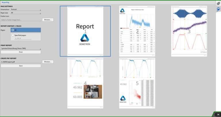
• Generate data results that conform to the test report according to the measured data, support the input of test report header files, and customize the report format.
• Data recorder: it can display the measured value/mean square value/average value in real time; Multiple display windows can be opened at the same time, and each window can display multiple channels. For example, on the right side of the figure below are different test interfaces. Users can add and delete at will, making testing as simple as doing a PowerPoint presentation.
• While supporting data acquisition, it can play back and analyze the past data in real time. The analysis function includes calculating large/small values, average values, effective values, frequencies, slopes, integrals, etc.
• Oscilloscope: multiple display windows can be opened at the same time, and each window can display 1~8 channels; With trigger mode function; It has the function of moving cursor to display data.
• X/Y recorder: display the relationship between the measured values of one or more channels and a channel.
• Spectrum analyzer: It has a high 262K spectral line resolution, multiple window functions (Hanning window (- 31dB), Hamming window (- 42dB), rectangular window (- 13dB), flat top window (- 68dB), blackman Harris (- 92dB) blackman (- 58dB) bartlett (- 26dB), etc.)
• Virtual channel of programmable operation: powerful online mathematical operation and filtering function. Including trigonometry, differential, integral, etc.
• Video recorder: synchronous video recording function.
• Integrated signal display instrument: display data recorder, oscilloscope, X/Y recorder, spectrum analyzer, video recorder, GPS map display, and other display instruments in various ways at the same time as required
• Analysis function: all test data are stored in real time, and can be replayed, selected, analyzed and printed.
• Flexible trigger function: level, time and frequency can be selected as trigger signals, and trigger conditions can be selected as edge trigger, filter edge trigger, pulse width trigger, slope trigger and other trigger methods. It supports setting and saving data N seconds before triggering. You can set the conditions for stopping storage and the time for storage.
• The sampling frequency can be set separately for each module. The sampling frequency can automatically convert the high and low speed sampling speed according to the trigger.
• Support GPS connection, complete synchronization with IRIG, and support PTP protocol, i.e. 1588 protocol.
• Provide user development package to realize secondary development.
• During multi-channel test, multiple data can be displayed in full screen and page by page. During full screen display, the hot key operation window can be switched without mouse operation. It is very suitable for remote multi-channel data acquisition and monitoring. It can review the stored data while recording data. The recorder supports convenient switching between full screen and non full screen viewing.
• Files can be output in multiple formats: Text, Excel, Flexpro, Matlab, etc.
main interface
Schematic diagram of channel display interface
Single channel setting interface
Schematic diagram of FFT and peak marking interface
Report production
5、 Test data cross-linking
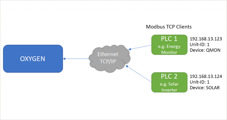
According to the requirements of some users, the data acquisition system has the ability to send the collected data to other designated data acquisition systems or computers/upper computers in real time. At present, the data acquisition system supports up to 350 channels with a sampling rate of 100ks/s per channel or 24 channels with a sampling rate of 2Ms/s per channel. It is equivalent to sending 48Ms/s sampling point data through TCP/IP every second.
The acquisition system implements data configuration through SCPI control interface protocol
Hardware communication port: TCP/IP
Data format: ASCII, source data type: uint32 (user self development is supported), and data format definition is shown in the following figure:
This is a set of 96 channel data acquisition system, taking strain, temperature and acceleration as the acquisition signals as examples, according to the product characteristics of DVC.


