Application and challenge of rocket test
The rocket has thousands of independent mechanical parts and technical subsystems, and their reliability is the main factor for the success of the rocket launch.
During the countdown before takeoff, the correct function of all these components must be monitored. This paper introduces a data acquisition system for monitoring the deformation, vibration and temperature of key points on the surface of a rocket during its development and launch countdown.
The challenge of rocket testing is that the signal conditioning and data exchange system must be in the bunker near the DUT to protect the system from the impact of the huge physical forces released during the launch of the rocket. For safety, the signal conditioning and data acquisition of the system are divided into several independent redundant subsystems. These subsystems are set in several locally distributed bunkers to avoid data loss in case of any unexpected and safety critical event. Of course, for safety reasons, it is not allowed to enter these bunkers during countdown and takeoff. Therefore, the data must be transferred to the control room from where the data acquisition system must be controlled.
Application Solution of DEWETRON
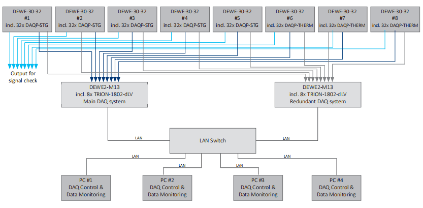
DEWETRON's solution for this complex application is divided into three different parts:
A 256 channel signal conditioning system
Two 256 channel data acquisition systems for redundant data storage
Data monitoring system composed of four independent workstations
The block diagram of the whole structure is shown in the figure above
Signal conditioning system
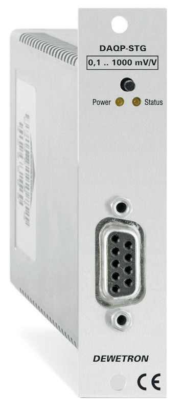
The signal conditioning system consists of 160 DAQP-STG modules, 96 DAQP-THERM modules and 8 DEWE 30-32 signal conditioning racks.
DAQP-STG and DAQP-THERM modules can obtain signals excited by constant voltage (up to 12V) and current (up to 20mA) from (full, half, 120 Ω and 350 Ω quarter) bridge sensors. In addition, RTD sensors (25 m Ω to 100 k Ω) and signals with voltages up to ± 10 V can be connected directly to these modules. The isolation signal conditioning path is fully simulated to ensure the highest reliability requirements. DAQP-THERM module (see Figure 3 on the right) supports a wide range of different types of thermocouples (K, J, T, R, S, N, E, B, L, C, U). At the output end, DAQP-STG and DAQP-THERM modules provide a condition ± 5 V signal for all these signals. The module can be programmed through the RS-485 interface.
DEWE-30-32 Signal conditioning rack
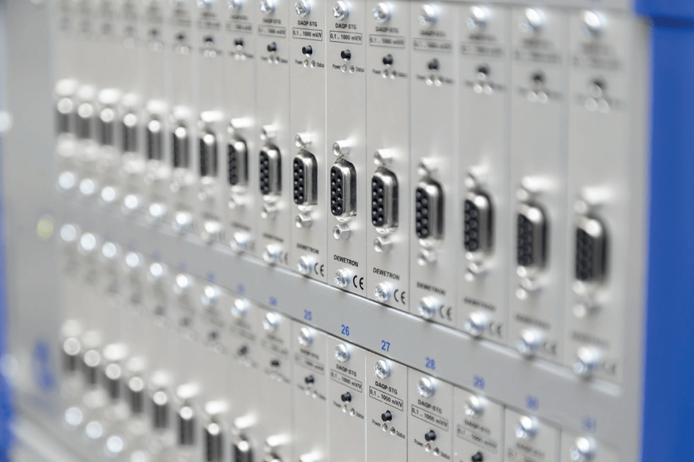
DEWE 30-32 rack is a signal conditioning rack with 32 slots of DAQP module.
The conditional ± 5v output signal of the DAQP module can be allocated to one, and two or even three measurement systems can be parallel (optional ± 10v output is also possible). Parallel signal output makes DEWE 30-32 a special signal conditioning solution for safety critical testing, and data loss must be avoided under any circumstances. It is only necessary to divide the data acquisition system into two or three redundant systems to prevent one of them from failing in critical safety or destructive tests. This safety critical application selects triple signal output. All signals are forwarded to two independent data acquisition systems to store data redundantly. The third signal output is reserved for sensor application and troubleshooting during signal check.
Data acquisition system DEWE2-M13
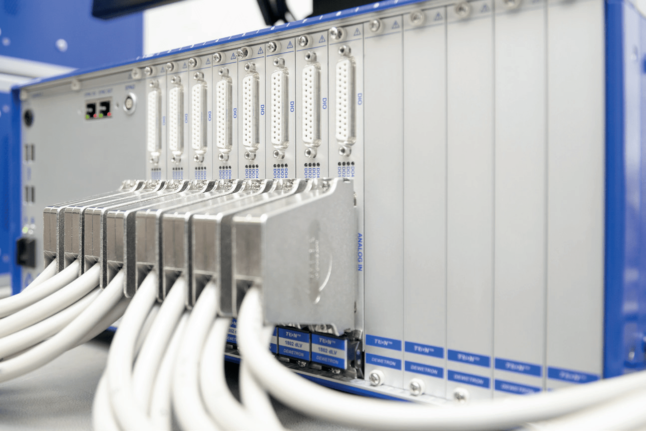
The TRION-1802-dLV board is used. The TRION-1802-dLV board provides 16 differential or 32 single ended input channels, up to ± 10v. Each channel uses a separate 18 bit SAR a/d converter for sampling, up to 200 kS/s. In addition, each channel provides a freely programmable optional on-board filter with optional second-order, fourth-order, sixth order or eighth order Bessel or Butterworth characteristics. In addition, the board also provides an RS-485 interface, 2 counter inputs, 1 CAN bus, 8 digital inputs and 4 digital outputs. The TRION-1802-dLV board is divided into two DEWE2-M13 data acquisition hosts on average. Each DEWE2-M13 is configured with 8 TRION-1802-dLV boards as an independent data acquisition system with 256 channels of input to carry out redundant digital processing for the signals of the DAQP module. Both DEWE2-M13 are connected to the other four desktop computers through Ethernet. The desktop PC is installed in the control room for data monitoring and trigger measurement, while the DEWE2-M13 is installed near the DUT to keep the cable length as short as possible.
OXYGEN Data acquisition software
DEWETRON's OXYGEN data acquisition software is the core component, which combines all these independent hardware components into a large, locally distributed, redundant measurement system. OXYGEN software runs on the DEWE2-M13 mainframe and stores data locally and redundantly on both systems. DAQP module configuration is also completed by OXYGEN software, because not only signal connection, but also RS-485 interface is installed between DEWE2-M13 and each DEWE 30-32. In addition, the OXYGEN software Ethernet transmitter plug-in outputs the signals obtained from the DAQP module through the UDP data stream at a lower sampling rate, and transmits the data to the desktop PCs in different control rooms. The OXYGEN software is also installed on the desktop computer.
At the receiving end, use the Ethernet receiver plug-in to decode the UDP data stream again. This function ensures that data can be distributed to different receivers. Each receiver can only visualize and monitor specific signals important to the system, and will not be interfered by other signals. When the signal reaches a certain threshold, the reduced data can be automatically stored on each desktop PC for analysis and post-processing. In addition, trigger commands can be sent to the DEWE2-M13 mainframe through Ethernet to control their recording status.
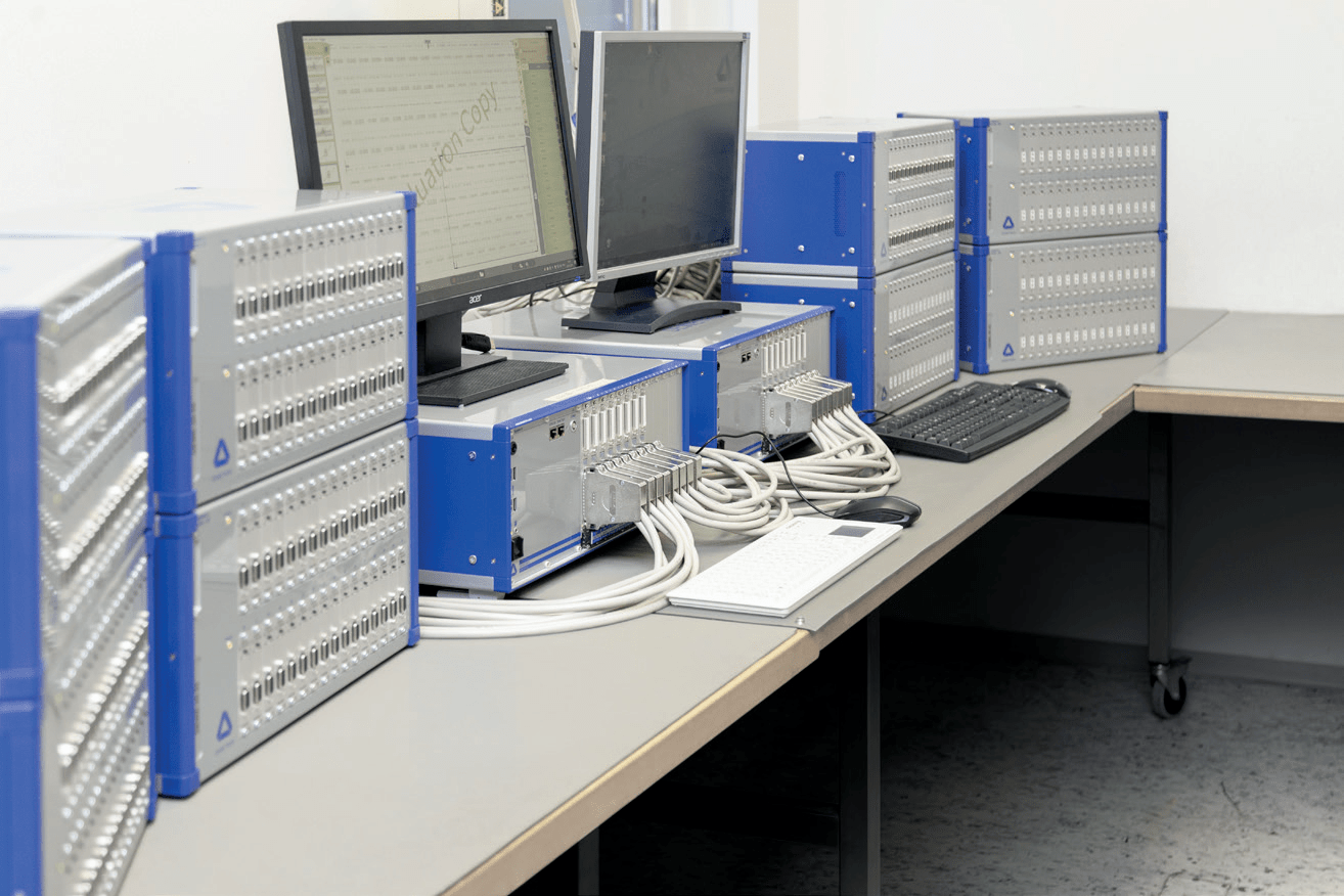
To sum up, the signal conditioning and data acquisition system consists of the following parts:
> 160x DAQP-STG
> 96x DAQP-THERM
>8x DEWE 30-32 has triple redundant signal output
> 2x DEWE2-M13
> 16x TRION-1802-dLV
>4x desktop
>6xOXYGEN data acquisition software
Benefits of using DEWETRON hardware for signal monitoring
Pure analog signal conditioning
DAQP-STG module provides pure analog signal regulator at the input end and conditional ± 5 V signal at the output end There is no digital component in the middle of the edge (see Figure 6). This ensures the highest reliability and turns the DAQP module into The signal conditioning scheme is preferred.
Redundant data acquisition
DEWE 30-32 signal conditioning rack provides single, double or triple analog signal output for each assembled DAQP module Put it on the shelf.
For this particular application, triple signal output is selected. This means that the condition ± 5v signal The output of each DAQP module can be picked up three times. On the one hand, transmit the signal to two independent data acquisition systems (DEWE2-M13) for data recording
On the other hand, one signal output is the reserved signal to check the troubleshooting in the sensor assembly and case. This means that even if one of the two independent data acquisition systems fails, the data will not be lost and will not be lost Available on the second mainframe.
Highly modular
If the DAQP-STG or DAQP-THERM signal conditioner needs to be calibrated or checked for use, then yes You may only unplug this specific signal conditioner and replace another one or leave the slot empty, while the rest The whole system is still operating normally. In addition, the single components of the system (DAQP module, DEWE 30-32 and DEWE2-M13) work independently and can be divided into several small data acquisition and signal conditioning systems.
High channel density
The TRION-1802-dLV board provides 16 differential or 32 single ended input channels (up to ± 10v) on a 37 pin DSUB connector. Each channel uses a separate 18 bit SAR a/D converter for sampling, up to 200 kS/s, and provides a selective on board low-pass filter. This board is combined with DEWE2-M13 to make your data acquisition system a high channel counting system. In a 19 inch rack, a single host only occupies 5U, and up to 416 analog input channels.


