Measurement of unsteady helicopter rotor flow introduce
This application case is a German customer's unsteady helicopter rotor flow measurement. The working group focuses on the aerospace field. Unsteady rotor blade aerodynamics shows the challenges faced by the working group. The team developed the measurement technology of unsteady flow and the application of aerodynamic analysis methods to rotating wings, as well as experimental and numerical tools. The development and validation of new technologies for detecting transient flow separation events, such as pressure sensor analysis or differential infrared thermal imaging, have played a role here.
Unsteady flow comes from the main rotor blades of the helicopter, whose main rotation period is 1-10 Hz, and additional pulse phenomena such as blade vortex interaction (BVI) or dynamic stagnation (DS). These aerodynamic phenomena are in the range of scientific visible light, so infrared cameras and high-speed lasers can be used to collect these data. Hot film anemometers and pressure sensors are also used to measure these phenomena. Despite the challenges and difficulties of measuring unsteady aerodynamic phenomena, they provide a significant expansion of the palette of aerodynamic situations. The Unsteady Aerodynamics Measurement Working Group focuses on aerodynamic similar test cases. A rotor with axial inflow is used to study the unsteady flow in a rotating system.
The working group installed a rotor test bench in Germany, where unstable flow is generated by a large cycle spacing and axial inflow, including the influence of centrifugal force and Coriolis force. The rotor adopts cyclic pitching operation, which means that the rotor blade changes its geometric angle of attack as the azimuth position, so every rotation executes a pitching cycle - similar to the pitching airfoil. In free flight, model scale and full-size helicopters are used for measurement to track the flow characteristics and verify the effect seen in the actual laboratory experiments on simplified helicopters.
In the past few years, the team has conducted a variety of different tests, including unsteady pressure measurement, unsteady boundary layer transition measurement and flow topology measurement. This paper only introduces the measurement results of unsteady pressure. Unsteady pressure measurement As a pressure sensor, two different high-speed micro pressure sensors from Kulite are used on the test bench to work as a full bridge strain gauge 。 There are two pressure sensor positioning methods depending on whether there is enough space. If enough space is available, it is usually possible to install large Approximately 50 sensors. If not, for example, in the small rotor blades on the test bench, only 10 sensors are installed 。

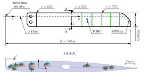
Instrument for rotor blade of German rotor test bench - two pressure sensors (r/R=0.53 and 0.77), PT100 and five PIV measurement planes are used
Application of Dewei Chuangchuang Data Recorder
DVC Data Recorder is used to obtain airfoil data. All channels are sampled synchronously. The sampling rate of the data recorder is fixed relative to the pitching rate of the airfoil, which means 1024 sampling values are obtained for each pitching cycle. The phase average of each measurement point is an average value, which is compared with computational fluid dynamics and different measurement points, as well as the standard deviation, which gives a measurement of the change from cycle to cycle. These come from vibration and turbulence on the structure or separated flow. For each angle of attack on the up and down strokes, there are pressure distributions and combined forces, which lead to inaccurate results. Phase averaging allows detection of dynamic motion at the boundary layer transition location. Pressure sensor analysis is only one of the four new technologies developed and validated by the helicopter aerodynamics team.


